NEWS | SOFTWARE | SHEET
A Complete Guide to Building Layouts for Successful Construction
The layout of a building is the first step in any construction project. In order for foundation marking and building layout to be accurate, they must be done with great care, as they cannot be changed after the work has been completed.
Engineers and architects lay out the foundation according to their foundation plans. Upon completion of the conditional survey and desk study, the layout of the building plan must be done.
A variety of variables include the total length and breadth, distances to the roadway centerline and other structures, interior structural measures, approaches and rights of way, etc.
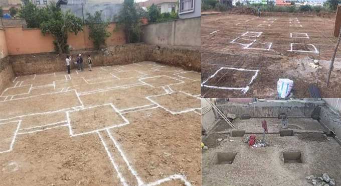
By displaying the foundation plan in drawings on a ground surface, excavation can be carried out with precision, so that the positions as well as orientation of the structure can be precisely determined.
This process is called Building Layout, and it involves controlling measurements and references on a drawing to determine the placement of the structure, especially its foundations.
Building Plan Drawings Types
Site Plan: The site plan shows how a building is laid out in detail. The plan shows the site's borders, including access points, as well as nearby structures that should be considered.
A historical site may be subject to restrictions under local development laws. For obtaining government approval for construction, it acts as an official agreement.
The site plan must be developed by a certified specialist, such as a landscape architect, architect, or engineer.
Floor Plan: A floor plan viewpoint shows the object from a vertical perspective on a horizontal plane that crosses through it.
There is a lot of detail in the floor plan that describes the layout of the rooms. No matter whether the plans will be used for the construction of a house, a store, or a commercial building, they are created.
Various types of installments and sizes are considered in the applications. It helps to gain an understanding of how the limited space should be used.
Elevation: Architects draw elevation diagrams to show the structure or part of a building. It is called an elevation when it shows a building's interior surface from a vertical position.
The same as you are standing directly in front of a structure and looking at it. Architects and engineers use elevations to represent buildings graphically as well as a popular design drawing.
An elevation diagram is an orthographic projection, which means there are no foreshortening and no perspective. Elevation diagrams are projection sketches of a single building's side.
Drawings of elevations show how a specific side of the house will look after it is finished, as well as providing vertical height measurements. A house is usually drawn with four elevations, one for each side.
Landscape Plan: Similarly to a floor plan, landscape design can be compared to an outdoor space. In the same way as a floor plan, a landscape design is a visual representation of a location using scaled measurements.
Landscape plans include natural elements like trees, flowers, and grass as well as manmade elements like garden furniture, waterfalls, and sheds. A landscape design also includes overlays for irrigation and lighting. There are many types of landscape plans, including private garden plans for the house and commercial plans for businesses.
Cross Section: Illustrations by cross section represent the house from the viewpoint of cutting the roof down and peering through the opening. The builder will be able to better understand the details of the interior and exterior construction with these perspectives. In the case of a complex housing design, there should be a greater number of cross sections.
Drawings showing cross sections provide information regarding wall and roof structure, external wall layers, staircase structure, and even interior features like soffits, cabinets, and ceiling heights.
Building Layout Methods
Excavation in Reduced Levels: Drawing a baseline will help you determine the overall outline of a low level area. By using dried sand or an equivalent material, the corner post is attached to the outline of the excavation area.
A traveler can be utilized to control the depth of the excavation by using sight rails that are at the appropriate height and place. Travelers are fixed height profiles used to manage excavation levels within profile boards.
Trenches: This plan determines directions, sizes, and shapes of the excavation, as well as the width and locations of walls. Excavation starts as soon as the outline of the building is established. A line of dots of lime powder is often used when excavating by hand, while a centerline is drawn when excavating by machine.
Often, outline profile boards are used to manage trench width, depth, and location. For excavation activity to be uninterrupted, the profile boards need to be placed no closer than 2 meters from trench excavation sites.
There is a common practice of hammering pegs into the trench bottom in order to indicate a top for the concrete strips that will be poured later. For accuracy, a spirit level is used to move a wall corner away from crossing cord lines.
When you are trenching, extreme caution should be used, particularly when they need to be left open for a considerable period of time.
To get more details, go through the following video tutorial.
Lecturer: RR Buildings
Framed Structures: Framed structures are generally interconnected to a grid and usually arranged along a baseline. Centers of isolated or pad foundations are indicated by grid line crossings.
Pegs are used to indicate grid intersections, along with the theodolite to draw out the grid. The offset pegs could be installed after the grid has been laid out so that future excavation operations do not interfere with them.
Controlling excavation depth can be achieved by using a traveler seen between sight rails or even a level attached to a site datum.


